Annals of Mathematics and Physics
Experimental Demonstration of Gravitational Impact on the Speed of Light
Enbang Li*
School of Physics, Faculty of Engineering and Information Sciences, University of Wollongong, Australia
Cite this as
Li E. Experimental Demonstration of Gravitational Impact on the Speed of Light. Ann Math Phys. 2025;8(4):096-101. Available from: 10.17352/amp.000154Copyright Licence
© 2025 Li E. This is an open-access article distributed under the terms of the Creative Commons Attribution License, which permits unrestricted use, distribution, and reproduction in any medium, provided the original author and source are credited.A cornerstone of Einstein’s special relativity is the postulation that light travels at a constant speed in a vacuum throughout spacetime, independent of the direction, location, time, and photon energy. The constancy and universality of the speed of light play an important role in modern physics for understanding the universe, and their validation has been demonstrated by various experiments and observations. Here we present a laboratory experiment to demonstrate that photons could interact with the Earth's gravitational field and consequently the speed of light would be affected by the Earth's gravity. The experimental results show that the speed of light increases with the gravitational field, and the variation fits with a test model proposed in this work. The findings of this study would open a new research direction on the interaction between photons and the gravitational field and could lead to exploring novel gravito-optic effects and photonics-based gravity detection technologies.
Introduction
The speed of light, denoted as c, is a fundamental constant in physics, representing the maximum speed at which all energy, matter, and information can travel. This constant has played an important role in the development of modern science, particularly physics. It took a long time before people concretely realised that light travels at a finite speed. In developing his famous equations, James Clerk Maxwell unified electricity, magnetism, as well as optics by describing light as an electromagnetic wave propagating at speed c [1]. In 1905, Albert Einstein postulated that the speed of light in a vacuum is constant and independent of the observer's motion in the special theory of relativity [2]. The speed of light c appears in the most famous formula 𝐸 = 𝑚𝑐2 and in the Einstein field equation of the general theory of relativity as a constant [3]. The speed of light also plays a crucial role in developing other modern physical theories [4], such as quantum electrodynamics [5], quantum chromodynamics [6], and the Standard Model of particle physics [7]. The constancy and universality of the speed of light not only make it a cornerstone in our understanding of the physical universe, but also underpin numerous technologies, including optical communications where fiber-optic cables transmit data as light pulses, enabling high-speed internet and telecommunications and the speed of light dictates data transmission rates and latency in these systems. In the Global Positioning System (GPS), satellites rely on precise time measurements to triangulate positions on Earth, so even minor inaccuracies in the speed of light would result in significant errors in location determination. Currently, the precise value of c in a vacuum is exactly 299,792,458 meters per second. This value has been utilised to redefine the metre, the standard of length unit [8].
Research on the speed of light has evolved from simple measurements to sophisticated theoretical and experimental investigations, addressing both its fundamental nature and practical implications [9]. Although it is still a mystery why the speed of light is the same in all inertial frames of reference, various experiments and observations (including the recently detected gravitational waves) have verified this assumption [10].
In a medium, light usually propagates at a speed that is different from c. This speed is dependent on the types of light waves and on a property of the medium, called susceptibility, which determines the refractive index of the medium [11]. As is well known, the refractive index of a material is a function of the light's frequency, intensity, polarization, or direction of propagation, and by applying external electric or magnetic fields to a material, its refractive index and hence the travelling speed of light in it can be modified and controlled. These electro-optic and magneto-optic effects have been thoroughly investigated and explored for a wide range of applications.
In modern physics, the postulation of the constant speed of light has become a cornerstone of both special and general theories of relativity and can be more generally expressed as the Lorentz invariance or Lorentz symmetry. Therefore, searching for Lorentz Invariance Violation (LIV) is now a major task to test the quantum gravity theories in which the quantum theory and the theory of general relativity will be merged into a unified framework. Detections of variations of the speed of light as a function of the photon energies or time are ways to test the existence of LIV, and various astronomical and cosmological observations have been carried out by utilising the electromagnetic radiations and neutrinos from gamma-ray bursts as well as the synchrotron radiation from numerous origins [12-17]. In optics and photonics research areas, superluminal and subluminal light speeds in free space have also been investigated by the introduction of transverse structure to the light beam or by controlling the group velocities of the space-time wave packets [18-20].
The general theory of relativity predicts that light waves or photon motions would be affected by the gravitational fields [21]; however, the interactions between gravity and light or photons, or any possible gravito-optic effects caused by the interactions, have not been widely investigated. Here we present a laboratory experiment to demonstrate that photons could interact with the Earth's gravitational field and consequently the speed of light would be affected by the Earth's gravity. The findings of this work will not only attempt to address one of the most fundamental issues in physics but also open a direction for developing photonics-based gravity detection technologies, which will find applications in mineral exploration as well as gravimetry for detecting unobservable structures.
Test model of the interaction between Earth's gravity and photons
The gravity generated by Earth is
where G is the Newtonian constant of gravitation, 𝑀⨁ is the mass of Earth, and R is the distance from the test point to the centre of Earth.
The dependence of g on R can be calculated as
As it would be expected, any possible interaction between the Earth's gravity and the photons should be extremely weak; hence, it is reasonable to assume that the speed of light is a function of g as
𝑐 (𝑔) = 𝑐0 [1+𝛼 (𝑔−𝑔0], (3)
Where 𝑐0 is the speed of light when the gravitational field is 𝑔0 and α is a parameter representing the dependence of the speed of light on the gravity. If α is positive, then the speed of light will increase with the gravity, and vice versa.
Therefore, if we can experimentally determine the sign and value of α, we can know whether the speed of light is increasing or decreasing with the variation of gravity.
Taking the differential of c concerning g, we have
or
If we let the light signals coming from a single source travel the same distance of L but under two different gravitational fields 𝑔1 and 𝑔2, and if the speed of light is gravity-dependent with the assumed form of Eq (3), a time delay would be produced and can be expressed as
On the Earth's surface, one can utilize the difference of the gravities at different heights to test if the speed of light has any dependence on gravity. The time delay can be expressed as
One way is to send an optical pulse to a distant reflector and measure the time when the light signal returns to the light source. If we carry out the tests at different altitudes above the ground surface, we could test if the speed of light is constant under the influence of the Earth's gravity. This type of experiment can be done in free space or using optical fibres. If in the free space, the tests will be on the speed of light, c. If in media such as optical fibres, the tests will be on the speed of light in the fibres, that is, the group velocity (𝑣𝑔).
If we carry out the tests at the ground where 𝑅 = 𝑅⊕ (the radius of Earth), and on a level H above the ground level where ∆𝑅 = 𝐻, by comparing the times used for a light signal traveling the same length at different gravities, we can test that if the Earth gravity would generate any impact on the speed of light in the fibre. Since normally 𝐻 ≪ 𝑅⊕, we can have
∆𝑡 = 2𝛼𝑔𝐿𝐻/𝑅⊕𝑣𝑔. (8)
Experiments and results
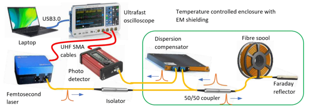
In order to experimentally demonstrate the test model described above, we designed an optical fibre system as schematically shown in Figure 1. (See Methods for more details). Laser pulses from a femtosecond fibre laser were sent to a spool of 10km optical fibre through an optical isolator and a 50/50 directional coupler. The laser pulses were reflected by an in-fibre Faraday mirror connected at the end of the fibre spool. In this way, the actual travel length of the laser pulses is 20 km. The reflected laser pulses coming out of the directional coupler were connected to a chromatic dispersion compensator to compress the broadened laser pulses. The compressed optical pulses were detected by an ultrafast photodetector, and the signals were recorded by a real-time digital oscilloscope with a signal bandwidth of 16 GHz and a sampling rate of 40 GSa/s. Since the transmission characteristics of the optical fibre are extremely sensitive to various environmental parameters, including temperature, pressure, and humidity, it is crucial to eliminate these effects from those caused by the change of gravity. To that end, we designed a temperature control system that maintains the temperature of all fibre-optic components and the fibre spool at a constant value during the experiments. A sealed enclosure with EM shielding was also built to isolate the air flows, which may cause changes in pressure and humidity during the experiments. The whole experimental system could be mounted on a trolley and transported for field tests. The trolley has four rubber tyres with low pressure to dampen any possible mechanical vibrations. The fibre laser and photodetector, as well as the temperature control system, were powered by a UPS power supply; therefore, there was no power interruption during the transfer of the experimental set-up.
In order to measure the time delays under different gravities, we carried out the tests inside the lifts in the buildings on campus. We set up the temperature at 30.0 °C for all of the tests. During the test period, the change of the temperature inside the enclosure was less than 1°C, and no change was observed on the digital displays of the temperature controllers. Therefore, it was believed that the temperature change of the optical system should be less than 0.1°C. The humidity inside the lifts was monitored by using a TRH22 digital relative humidity meter, and no obvious changes were observed during the test period. The air pressures in the lifts and inside the enclosure were measured with a Testo 512 digital manometer. The pressure inside the enclosure was constant while the pressure in the lifts changed with the height within a range of 1.3 hPa.
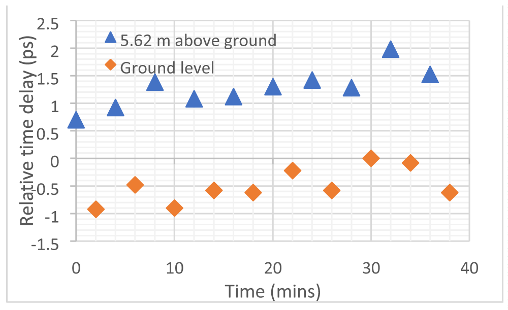
Tests were carried out in an equal time manner, that is, one measurement was done at one level and then at another level in two minutes' time, and tests were repeated multiple times. For every measurement, more than 1000 data points were collected for 30 seconds for each height level, and then the mean and standard deviation values were calculated. The resolution of the delay measurement is 0.1 ps, and the standard deviations of time delay measurements were in the picosecond range. The measurement results presented below were the averaged time delays, and the error bars were calculated from the multiple tests made under the same conditions.
Shown in Figure 2(a) are the measured relative time delays for the ground level and those for a level of 5.62 m above the ground level. It can be seen that different time delays have been detected when the measurements were carried out at different height levels. With the experimental set-up we built, we believe that the only factor which could cause the delay difference would be the different gravitational fields at the two levels. It is also clear that the light pulses take a longer time traveling at a level above the ground level than on the ground level, where the gravitational field is stronger. This demonstrates that the speed of light in the optical fibre would increase with the gravitational field.
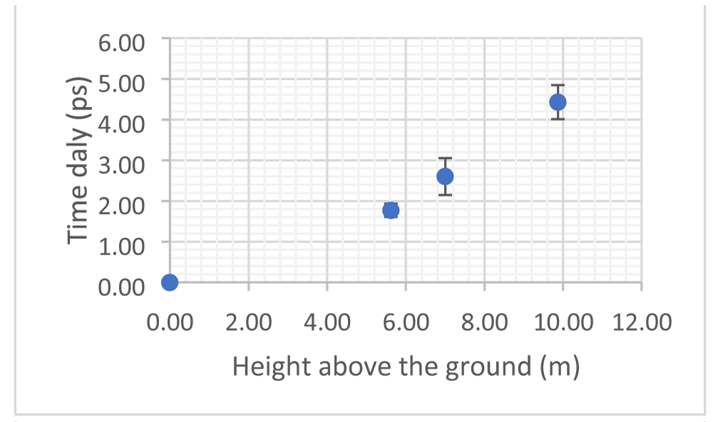
In order to further verify the above results, we conducted more tests in the same lift but with a height difference of 9.87 m, and also inside a second lift in another building by selecting a height difference of 7.0 m. For all of the tests carried out, we took the ground level as the reference to calculate the time delay difference between the time delay at a level and that measured in two minutes at the ground level to minimise any possible influences other than the difference in gravity. Plotted in Figure 2(b) are the time delays measured at different levels above the ground level. It is obvious that the time delay increases with the height above the ground level following a nearly linear relation, which further demonstrates that the speed of light traveling in the optical fibre increases with the Earth's gravity. From the measured data, we can obtain an average slope and by employing Eq (8) with the following parameters: L = 20 km, 𝑅⊕ = 6378 𝑘𝑚 and 𝑣𝑔 = 3 × 10⁵/1.4682 = 2.043 × 10⁵𝑘𝑚/𝑠, we can calculate 𝛼 = 1.37 × 10⁻²𝑠2/𝑚.
Methods
An ultrafast erbium fiber laser system, FemtoFiber pro (from TOPTICA Photonics), is used as the light source in the experimental setup, as shown in Figure 1. The master-oscillator of the FemtoFiber pro operates at 80 MHz repetition rate for the 1560 nm fundamental wavelength. The average power of the seed laser pulses from the FC/APC fibre output port is 1 mW, and the pulse width (after a 2 m long fibre patch cord) is measured as 550 fs by using an autocorrelator. The optical fibre used in the experiments is 10 km long SMF28e (G.652.D) fiber in a spool of 23 cm (D) x 11 cm (H). In order to maintain the laser pulse shape after the return transmission of 20 km fibre length, a dispersion compensation module (DCMS-SM-C100%-020-LCP-05, from Yangtze Optical System Corp. Ltd, Wuhan, China) is employed to compensate the chromatic dispersion generated by the fibre. An ultrafast photodetector (DXM30BF, from ThorLabs) with a bandwidth larger than 30 GHz in the 750 nm - 1650 nm wavelength range is used to convert the optical signal to an electrical signal. The equipment used for real-time pulse recording is a digital oscilloscope (RTP164B, from Rohde & Schwarz) with a signal bandwidth of 16 GHz and a sampling rate of 40 GSa/s. The laser pulse width directly measured by using the photodetector and the digital oscilloscope is 90 ps, which is limited by the bandwidths and time responses of the measurement instruments.
In order to precisely measure the delay time of the laser pulses after traveling 20 km long optical fibre, the RF-Sync output (ie, the Oscillator Monitor Output) from the FemtoFiber pro is used as the triggering signal for the digital oscilloscope to record the detected laser pulses. Therefore, by measuring the pulse peak position, we can achieve measurements of the delay time. The resolution of the delay measurement is 0.1 ps. A MATLAB code has been developed for transferring the measurement data from the digital oscilloscope to a laptop computer.
In order to achieve precise temperature control for the optical system, two copper enclosures, one for the fibre spool and another for other optical components, are manufactured. Silicone rubber heating wires are uniformly wound around the enclosures as the heating elements and 2 cm-thick insulating foams are glued to the outsides of the enclosures for thermal insulation and sealing purposes. The copper enclosures are also electrically grounded to shield against any possible EM interference. PT100 temperature sensors are attached to the copper enclosures and connected to two independent digital temperature controllers. All the passive components of the optical system are arranged in a plastic box to further isolate the optical components from the environment.
Discussion and conclusion
In 1911, Einstein considered the variation of the speed of light caused by the gravitational time dilation and predicted that the speed of light would vary with the gravitational potential ϕ following the relation , where 𝑐0 is the speed of light that Einstein defined at the coordinate origin [22]. If we compare this equation with Eq.(3) and by considering the Earth's gravitational field, we can readily obtain an expression for the constant α in Eq.(3) as 𝛼 = 𝑅⊕/𝑐2. By using the parameters for our experiments, we have 𝛼 = 1.6 × 10⁻¹⁰𝑠2/𝑚, which is 8 orders of magnitude smaller than the value determined by the experiments. This could demonstrate that it is the gravity g rather than the gravitational potential ϕ that affects the speed of light.
In our experiments, we tried all possible measures to rule out other causes of the time delay, including temperature, air pressure, and stress, as well as humidity, which may affect the refractive index of the optical fibre. Another factor that could also affect the speed of light in the fibre loop is the Sagnac effect caused by the rotation of the laboratory frame. Since the Sagnac effect would be the same for the different height levels, there would be no impact on the experimental results reported here.
In conclusion, we have experimentally demonstrated that the speed of light in optical fibres increases with the Earth's gravity g. To the best of our knowledge, this is the second experiment aiming to verify the interactions between the photons and the Earth's gravitational field in laboratory environments after the famous Pound–Rebka experiment carried out in 1959 on the gravitational redshift [23]. The tests presented here can be repeated and verified in most optics and photonics laboratories. It should be stressed that the speed of light discussed here is the local speed (proper speed of light) rather than the coordinate speed of light observed by a distant observer, and the reported results are for optical fibres. The mechanism responsible for the observed phenomena is unknown and should be further investigated.
Data availability
Data sets generated during the current study are available from the corresponding author on reasonable request.
The author would like to thank Roger Lewis, Anatoly Rosenfeld and Michael Lerch for their supports and useful discussions. The technical supports provided by Tristen Tan and Raja Pillai from Rohde & Schwarz Australia Pty Ltd are also acknowledged.
Appendix
In the general theory of relativity, different speeds of light are utilised.
Coordinate the speed of light
In the Schwarzschild geometry, considering the photon motion in the equatorial plane, the equations of photon motion are given by the null geodesic equations. From there, we can derive the coordinate radial speed of light as (Hobson, M. P., Efstathiou, G.P. and Lasenby, A. N. General Relativity: An Introduction for Physicists, Cambridge University Press 2006)
This indicates that the coordinate speed of light is gravity-dependent and decreases when gravity increases.
Physical (or proper) speed of light
The proper speed of light (also in radial direction), which is physical and measurable, is defined as
We can also show that the proper speed of light in the tangential direction is also c, which is consistent with the postulate made in the general theory of relativity.
The difference between the coordinate speed of light and the physical (or proper) speed of light can also be found from a paper published in 2020 (Benedetto, E., Feleppa, F. & Sersante, B. On the distinction between coordinate and physical speed of light in general relativity. Afr. Mat. 31, 793– 802, 2020).
Shapiro time delay
The calculation of the Shapiro time delay is based on the coordinate speed of light (see, for example, Page 237 of Hobson, M. P., Efstathiou, G.P. and Lasenby, A. N. General Relativity: An Introduction for Physicists, Cambridge University Press 2006). The Shapiro time delay is the accumulated delay caused by the change of the coordinate speed of light along the return path from the Earth to a reflective object.
- Maxwell JC. VIII. A dynamical theory of the electromagnetic field. Philos Trans R Soc London. 1865;155:459-512. Available from: https://doi.org/10.1098/rstl.1865.0008
- Einstein A. Zur Elektrodynamik bewegter Körper. Annalen der Physik. 1905;322:891-921. Available from: https://doi.org/10.1002/andp.19053221004
- Einstein A. Die Grundlage der allgemeinen Relativitätstheorie. Annalen der Physik. 1916;354:769-822. Available from: https://doi.org/10.1002/andp.19163540702
- Serway RA, Moses CJ, Moyer CA. Modern Physics. Cengage Learning; 2004. Available from: https://books.google.co.in/books/about/Modern_Physics.html?id=uTM8AAAAQBAJ&redir_esc=y
- Jentschura UD, Adkins GS. Quantum Electrodynamics: Atoms, Lasers And Gravity. World Scientific Publishing Company; 2022. p. 812. Available from: https://doi.org/10.1142/12722
- Kovchegov YV, Levin E. Quantum Chromodynamics at High Energy. Cambridge University Press; 2023.
- Grossman Y, Nir Y. The Standard Model: From Fundamental Symmetries to Experimental Tests. Princeton University Press; 2023. Available from: https://api.pageplace.de/preview/DT0400.9780691239118_A46419645/preview-9780691239118_A46419645.pdf
- Mares JJ, Hubik P, Spicka V, Stavek J, Sestak J, Kristofik J. Shadows over the speed of light. Physica Scripta T. 2012;151:014080. Available from: http://dx.doi.org/10.1088/0031-8949/2012/T151/014080
- Grandy D. The Speed of Light: Constancy + Cosmos. Indiana University Press; 2009. p. 216. Available from: https://books.google.co.in/books/about/The_Speed_of_Light.html?id=joKTepFH4WkC&redir_esc=y
- Abbott BP, Abbott R, Abbott TD, Abernathy MR, Acernese F, Ackley K, et al. Observation of Gravitational Waves from a Binary Black Hole Merger. Phys Rev Lett. 2016;116:061102. Available from: https://doi.org/10.1103/PhysRevLett.116.061102
- Jackson JD. Classical electrodynamics. 2nd edn. Wiley; 1975. Available from: https://www.sciepub.com/reference/409099
- Amelino-Camelia G, Ellis J, Mavromatos N, Nanopoulos D, Sarkar S. Tests of quantum gravity from observations of γ-ray bursts. Nature. 1998;393:763-765. Available from: http://dx.doi.org/10.1038/31647
- Jacobson T, Liberati S, Mattingly D. A strong astrophysical constraint on the violation of special relativity by quantum gravity. Nature. 2003;424:1019-1021. Available from: https://doi.org/10.1038/nature01882
- Jacob U, Piran T. Neutrinos from gamma-ray bursts as a tool to explore quantum-gravity-induced Lorentz violation. Nat Phys. 2007;3:87-90. Available from: https://www.nature.com/articles/nphys506
- Abdo AA, Ackermann M, Ajello M, Asano K, Atwood WB, Axelsson M, et al. A limit on the variation of the speed of light arising from quantum gravity effects. Nature. 2009;462:331-334. Available from: https://ui.adsabs.harvard.edu/link_gateway/2009Natur.462..331A/doi:10.1038/nature08574
- Addazi A, Alvarez-Muniz J, Batista RA, Amelino-Camelia G, Antonelli V, Arzano M, et al. Quantum gravity phenomenology at the dawn of the multi-messenger era-A review. Prog Part Nucl Phys. 2022;125:103948. Available from: https://ui.adsabs.harvard.edu/link_gateway/2022PrPNP.12503948A/doi:10.1016/j.ppnp.2022.103948
- Song H, Ma B. Examining Lorentz invariance violation with three remarkable GRB photons. Phys Dark Universe. 2025;47:101808. Available from: https://doi.org/10.1016/j.dark.2025.101808
- Giovannini D, Romero J, Potoček V, Ferenczi G, Speirits F, Barnett SM, et al. Spatially structured photons that travel in free space slower than the speed of light. Science. 2015;347:857-860. Available from: https://doi.org/10.1126/science.aaa3035
- Kondakci H, Abouraddy A. Optical space-time wave packets having arbitrary group velocities in free space. Nat Commun. 2019;10:929. Available from: https://doi.org/10.1038/s41467-019-08735-8
- Yessenov M, Free J, Chen Z, Johnson EG, Lavery MPJ, Alonso MA, et al. Space-time wave packets localized in all dimensions. Nat Commun. 2022;13:4573. Available from: https://doi.org/10.1038/s41467-022-32240-0
- Blandford RD. A century of general relativity: Astrophysics and cosmology. Science. 2015;347:1103-1108. Available from: https://doi.org/10.1126/science.aaa4033
- Einstein A. The influence of the force of gravity on the dispersion of light. Annalen der Physik. 1911;340(10):898-908. Available from: https://doi.org/10.1002/andp.19113401005
- Pound RV, Rebka GA Jr. Gravitational red-shift in nuclear resonance. Phys Rev Lett. 1959;3:439-441. Available from: https://doi.org/10.1103/PhysRevLett.3.439
 Help ?

PTZ: We're glad you're here. Please click "create a new query" if you are a new visitor to our website and need further information from us.
If you are already a member of our network and need to keep track of any developments regarding a question you have already submitted, click "take me to my Query."
